Inicio >>
CROSSLEE >>
G447S.FERRONAMK2 Manual de Usuario
0 artículo(s) en Su carrito
Opiniones de los clientes
No hay comentarios de productos.
TEXT_PDF_SNIPPET
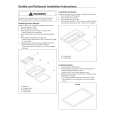
Page 4 Site the appliance as far back as possible whilst maintaining a central position in the opening, establish where the fixing holes are to be. A bracket is supplied in the fixing kit; this can be located either to the front or to the rear of the fascia panel. To the rear the fixing holes will probably coincide with a concrete base within the opening which will prevent drilling into a marble hearth etc, access to these two holes would be through two of the large holes above the fascia panel. Alternatively the bracket can be reversed to allow access to the front of the fascia panel see fig. 3. Having decided the preferred position, mark and drill suitable holes for the fixing plugs and screws provided and screw the appliance in position. CONNECTING THE GAS SUPPLY Determine where the gas supply is to be connected to the appliance. This may be made from the front of the unit from either the left or right side or, a concealed fitting from the rear of the inlet elbow. TURN OFF ANY APPLIANCES THAT ARE FED BY THE METER AND ISOLATE THE GAS SUPPLY BY TURNING OFF AT THE METER. If the supply is to be a concealed connection it would be advisable to route the supply to the left side of the unit taking into account the requirements of BS 6891:1988 dealing with enclosed pipes. This standard requires that when a gas pipe is fed through a wall, it should be enclosed in a gas tight sleeve to protect against failure caused by movement and shall be constructed to prevent passage of gas either between the pipe and sleeve or sleeve and wall. Connections may be made from the front of the appliance from either the left or right in 8 mm diameter pipe, if a right hand connection is required the tube should be routed across the front of the fascia panel by rotating the inlet elbow to the required position. See fig 4. A suitable isolating cock or restrictor elbow should be fitted close to the appliance to facilitate servicing. TO CHECK THE APPLIANCE SETTING PRESSURE. The pressure test point at the inlet elbow enables verification of the inlet pressure at the appliance under operating conditions and can also be used to check the gas soundness of the connections to the appliance gas control. SETTING UP THE COAL BED. (See the identification sheet on page 8) Components 2 burner inserts. 16 Large Coals. Coal support shelves (L&R hand). 4 Medium Coals. Artificial coal front. 2 Triangular Coals Place the left and right coal support shelves with the rebate on the underside, over the rear flange of the support channel. Place the two Tee shaped burner inserts into the channel between the front and rear ports of burner. Locate the fibre artificial coal front on the shelf above the fascia panel. Figures 4 & 5. Note. If any of the coals or the coal bed becomes damaged, lost or broken, replacements must be obtained before the appliance is used. COAL LAYOUT First Layer. Position 3 large coals with their rear edge on the burner inserts. Place 4 coals at the rear of the coal support shelf and lay 5 more across as a middle row. See fig. 6. Two triangular coals are placed one either side of the front row ensuring that the one on the right does not lay on the pilot assembly. Second Layer. Position the remaining 4 large with the 4 medium coals in the positions shown in fig.7. To obtain the best visual appearance it may be necessary to make slight adjustments to the position of the coals. NOTE: Additional coals must not be used